
1. Customer Requirements Assessment
Before a single component is selected, our design team works directly with the customer to define the exact performance parameters of the unit. This stage ensures the compressor is built right the first time — eliminating costly retrofits or under-specced equipment down the road.
- Tank capacity & orientation — Horizontal or vertical configuration; sizing matched to CFM demand and duty cycle (e.g., 60 gal, 80 gal, 120 gal or even 240 gal)
- Horsepower selection — From fractional HP for light-duty intermittent use to 30HP for continuous industrial applications
- Voltage & phase — Single-phase (120V / 240V) or three-phase (208V / 575V) depending on facility electrical supply. We also
- Operating pressure (PSI) — Target cut-in and cut-out pressures; maximum working pressure validated against tank rating and safety valve specs
- Compression stage — Single-stage (up to ~150 PSI, general purpose) vs. two-stage (up to 175+ PSI, high-demand or continuous duty) pump selection
- Duty cycle & environment — Indoor vs. outdoor placement, ambient temperature range, moisture considerations, and regulatory requirements (CSA, ASME, etc.)

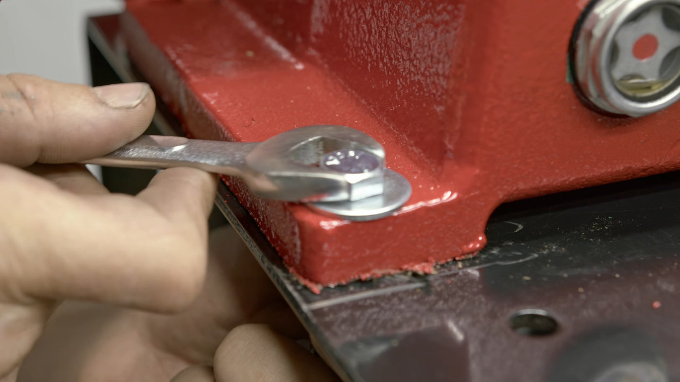
2. Tank Preparation & Fitting Installation
The receiver tank is the structural backbone of the compressor. Our team preps each tank to exact specifications before any mechanical assembly begins, ensuring pressure integrity and a leak-free system from day one.
- Visual and dimensional inspection of ASME-rated receiver tank (certifications verified before build)
- Installation of NPT fittings: inlet, outlet, drain valve, pressure gauge port, and safety relief valve connection
- Mounting of pressure switch manifold with appropriately rated fittings and sealing compounds
- Tank legs or saddle mounts installed and torqued to specification
- Thread sealant and pressure-rated pipe dope applied at all threaded connections; no PTFE tape used where prohibited by spec
- Tank ID plate reviewed and logged for traceability through final certification

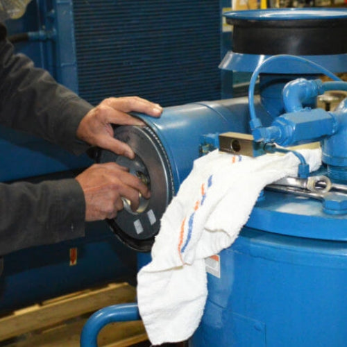
3. Pump & Motor Installation
Precise alignment between the motor and the pump is critical to minimizing vibration, extending belt and bearing life, and achieving rated CFM output. This stage requires careful shimming and measurement — not guesswork.
- Motor and pump mounted to the cradle or base plate; all hardware torqued per manufacturer specification
- Sheave (pulley) faces aligned using a straight-edge or laser alignment tool to eliminate angular and parallel misalignment
- Motor centred and positioned to achieve correct belt tension at final assembly
- Pump inlet filter / air filter installed; oil fill verified to correct level for splash-lubricated units
- Head gaskets inspected on pump; valve plates confirmed seated properly before assembly is secured
- Pump-to-tank discharge connection completed with appropriate check valve and flexible hose/connector

4. Pulley, Belts & Belt Guard
The belt drive is the mechanical link between the motor and the pump. Proper selection and installation of pulleys and belts directly determine the pump's operational RPM — and therefore its CFM output and longevity.
- Drive and driven sheaves selected to achieve target pump RPM based on motor speed and pulley ratio calculations
- V-belt(s) — typically A or B series — selected for load rating and matched in length for multi-belt setups
- Belt tension set to manufacturer specification using a tension gauge (not by feel); verified for correct deflection under load
- Sheave set screws torqued and shaft keys confirmed seated before final tightening
- CSA-compliant metal belt guard installed, fully enclosing rotating drive components; guard hardware secured and captive to prevent accidental removal
- Rotation direction of pump confirmed correct before energizing

5. Starter Installation & Electrical Wiring
All Airtek units are wired following CSA standards. Proper motor starting and overload protection is non-negotiable in industrial environments — both for operator safety and equipment longevity.
- Magnetic starter or pressure switch assembly mounted in appropriate enclosure (NEMA 1 indoor or NEMA 4 / 4X where moisture or wash-down is a factor)
- Overload relay set to motor FLA (full load amps) per nameplate rating; thermal protection confirmed
- Motor leads wired for correct voltage connection (low/high voltage configuration verified against supply voltage)
- Pressure switch wired and set for correct cut-in / cut-out pressure differential; unloader valve function confirmed
- All wiring dressed, strain-relieved, and labelled; terminal connections torqued to specification
- Ground continuity verified from motor frame to supply ground; electrical safety checks completed prior to energizing

6. Commissioning & Pressure Testing
No unit ships without a full functional test. Our commissioning process validates the performance, safety, and reliability of every compressor under load — simulating real operating conditions before the unit ever reaches your facility.
- Initial run-in cycle: motor and pump operated under no-load, then progressively loaded to verify smooth startup and operation
- CFM output measured and compared against rated specification; discrepancies investigated before sign-off
- Pressure switch cut-in and cut-out confirmed at set points; differential verified to be within specification
- Safety relief valve tested to confirm it opens below maximum allowable working pressure (MAWP)
- All fittings leak-tested under full system pressure using an approved detection method (soap solution or electronic leak detector)
- Final inspection sheet completed, serialized, and archived; unit tagged and prepared for delivery or pickup
-

Canadian Manufacturing
Assembled and tested domestically — faster lead times, easier service access, and full support from our team.
-

ASME Certified
All units meet applicable Canadian safety standards and ASME-rated pressure vessels.
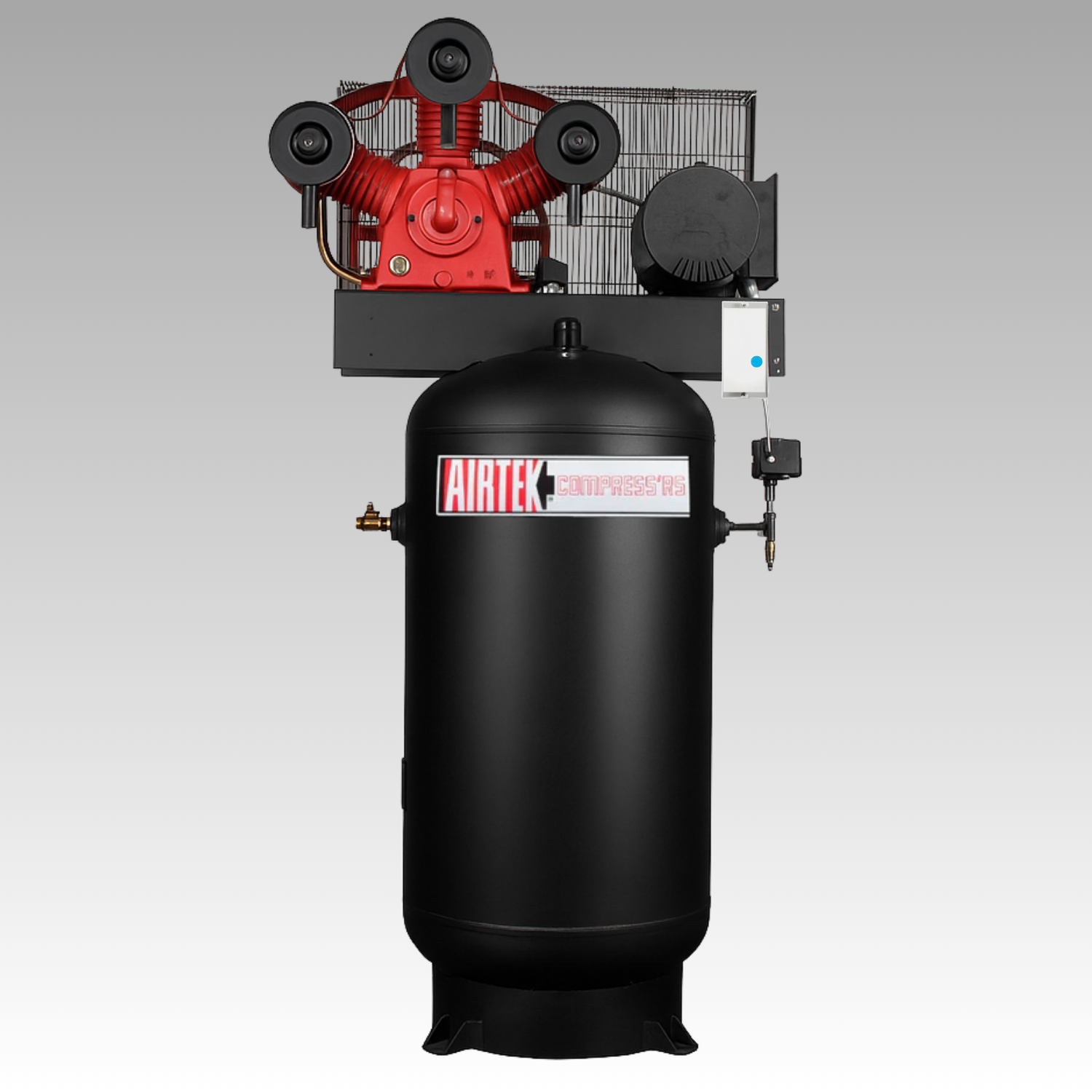
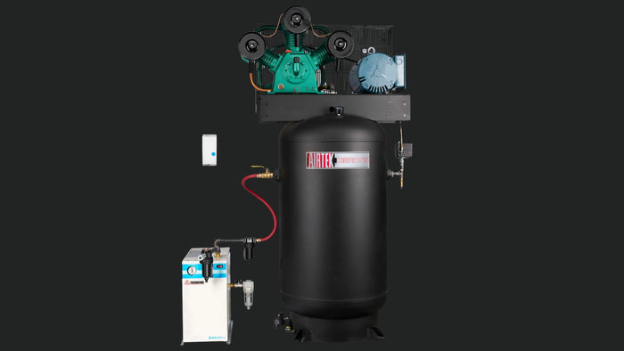
Vertical Electric Industrial Air Compressor Series - with Magnetic Starter - 3 HP / 60 Gallons / Single Stage is backordered and will ship as soon as it is back in stock.
Where Our Industrial Air Compressors perform best


Keep Your Compressor Running Strong
-
Maintenance
We offer essential maintenance tips to help you keep your air compressor in top condition. Regular maintenance is crucial for maximizing efficiency and extending the lifespan of your equipment. Key recommendations include:
- Regular Oil Checks: Ensure proper oil levels for smooth operation and to prevent wear.
- Filter Maintenance: Clean or replace air filters regularly to maintain airflow and efficiency.
- Inspect Hoses and Connections: Check for wear and leaks to ensure a secure and reliable system.
- Moisture Management: Regularly drain the tank to prevent corrosion and maintain air quality.
-
Parts
We offer a comprehensive range of OEM parts to keep your air compressor operating at its best. Our selection includes:
- Pumps
- Motors
- Check valves
- Air Compressor Tanks
- Belt guards
- Pressure switches
- Electronic time drains
- Safety valves
- Magnetic starters
And more.
-
Service
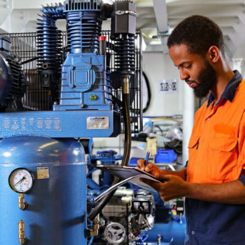
We offer professional inspection and service for your air compressors to ensure they operate at peak efficiency. Our dedicated team is here to assist with:
- In-Depth Inspections: Bring your air compressor in for a thorough assessment of any potential issues.
- Oil Replacement: We’ll replace oil to maintain optimal performance.
- Component Installation: Expert installation of new components to enhance functionality and reliability.
- Repairs: Fast and reliable repairs to get your compressor back to work quickly.


